
IoT Hacking - Spawning UART shells
Introduction
Hacking IoT devices to identify vulnerablities using UART is a common way to gain access to the IoT device when you have physical access to the device. UART stands for universal asynchronous receiver / transmitter and defines a protocol, or set of rules, for exchanging serial data between two devices. UART is very simple and only uses two wires between transmitter and receiver to transmit and receive in both directions. Both ends also have a ground connection.
Allmost all IoT hardware have the UART functionality onboard, because it is used for debug purposes. To identify the UART interfac and ports, you will need to open the device to gain access to the process circuit board (PCB) and UART interface.
Identifying UART Ports
UART has 4 ports: TX(Transmit), RX(Receive), VCC(Voltage), and GND(Ground). You might be able to find 4 ports with the TX and RX letters written in the PCB.
But if there is no indication, you might need to try to find them yourself using a multimeter or a logic analyzer.
With a multimeter and the device powered off:
- To identify the
GNDpin
Use the Continuity Test mode, place the back lead into ground and test with the red one until you hear a sound from the multimeter.
Several GND pins can be found the PCB, so you might have found or not the one belonging to UART.
- To identify the
VCCport
Set the DC voltage mode and set it up to 20 V of voltage. Black probe on ground and red probe on the pin. Power on the device.
If the multimeter measures a constant voltage of either 3.3 V or 5 V, you’ve found the VCC pin. If you get other voltages, retry with other ports.
- To identify the
TXport
DC voltage mode up to 20 V of voltage, black probe on ground, and red probe on the pin, and power on the device.
If you find the voltage fluctuates for a few seconds and then stabilizes at the Vcc value, you’ve most likely found the TX port.
This is because when powering on, it sends some debug data.
- The
RXport would be the closest one to the other 3
It has the lowest voltage fluctuation and lowest overall value of all the UART pins.
Getting an UART shell on the Transpeed 6K Ultra HD TV Box
Let’s do a quick demonstration how to get an UART shell running on a Transpeed 6K Ultra HD TV Box. You will need a Transpeed Ultra 6K device, a multimeter and I am using a Flipper Zero device to setup an UART bridge between the IoT device and my Macbook Pro.
The Flipper Zero is a portable multi-functional device developed for interaction with access control systems with a curious personality of a cyber-dolphin. The device is able to read, copy, and emulate RFID and NFC tags, radio remotes, iButton, and digital access keys, along with a GPIO interface. The idea of Flipper Zero is to combine all the hardware tools you’d need for exploration and development on the go.
Finding the UART Interface on the Transpeed 6K Ultra HD
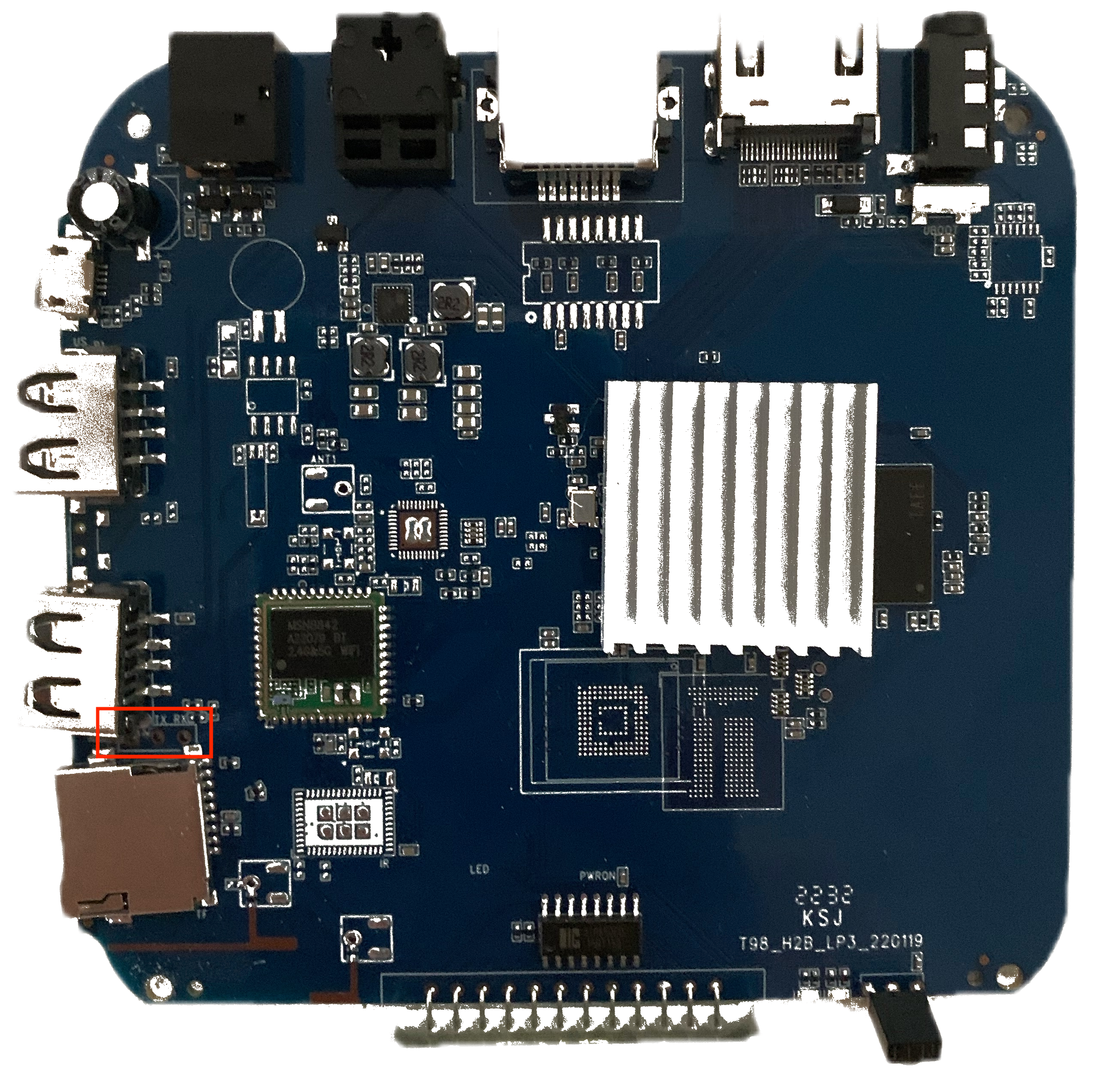
The Transpeed 6K Ultra HD is a low-end TV Box running Android V10 with a Quad Core with ARM Cortex-A53 processors. After opening the device (remove the four plastic buttons at the bottom to acces the screws and unscrew the box), you can detach the PCB and check for the UART interface.
In this case, is it rather simple to identiy the UART interface because the RX and TX ports are marked on the board (see red rectangle)
which makes the testing of the ports with the multimeter redundant.

Spawning a Shell
Now that we have identified the UART interface, you can connect the UART ports RX, TX and GND to your Flipper Zero as indicated on the diagram below.
Connect your Flipper Zero to your Macbook Pro or other PC with USB and select GPIO->USB-UART Bridge option and set the baudrate to 115200, 8 bits, no partity and 1 stopbit.
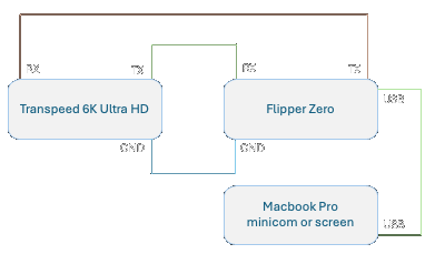

Use minicom or screen to configure the serial device interface on your Macbook.
Please ensure that you use the same baudrate settings and select the flipper serial device.
In my case the serial device is named /dev/tty.usbmodemflip_On71nere1.
╭─ ~ ······························································································································· 2m 53s 09:58:36
╰─❯ minicom -s
+-----------------------------------------------------------------------+
| A - Serial Device : /dev/tty.usbmodemflip_On71nere1 |
| B - Lockfile Location : /usr/local/Cellar/minicom/2.9/var |
| C - Callin Program : |
| D - Callout Program : |
| E - Bps/Par/Bits : 115200 8N1 |
| F - Hardware Flow Control : No |
| G - Software Flow Control : No |
| H - RS485 Enable : No |
| I - RS485 Rts On Send : No |
| J - RS485 Rts After Send : No |
| K - RS485 Rx During Tx : No |
| L - RS485 Terminate Bus : No |
| M - RS485 Delay Rts Before: 0 |
| N - RS485 Delay Rts After : 0 |
| |
| Change which setting? |
+-----------------------------------------------------------------------+
Start minicom and power on the Transpeed 6K Ultra HD device. You will see a lot of boot messages and at some point you will be able to enter a shell.
In my case, boot messages kept coming and I had to adjust the debug level with the command dmesg -n 1 to silence the console.
If you have garbled output please check that your UART ports are connected properly according to the UART connection diagram listed above.
Do not forget the GND pins and check your baudrate settings on both sides (minicom and Flipper Zero).
╭─ ~ ······························································································································· 2m 53s 09:58:36
╰─❯ minicom
... Lot of boot messages ...
[ 85.826256] type=1400 audit(1654132468.583:93): avc: denied { open } for comm="d.process.media" path="/dev/gsm" dev="tmpfs" ino=1222 scontext=u:r:mediaprovider:s0:c512,c768 tcontext=u:object_r:device:a
[ 85.827383] type=1400 audit(1654132468.720:94): avc: denied { read write } for comm="ocess.gservices" name="gsm" dev="tmpfs" ino=1222 scontext=u:r:priv_app:s0:c512,c768 tcontext=u:object_r:device:s0 ts
[ 85.827634] type=1400 audit(1654132468.720:94): avc: denied { read write } for comm="ocess.gservices" name="gsm" dev="tmpfs" ino=1222 scontext=u:r:priv_app:s0:c512,c768 tcontext=u:object_r:device:s0 ts
[ 85.829174] type=1400 audit(1654132468.720:95): avc: denied { open } for comm="ocess.gservices" path="/dev/gsm" dev="tmpfs" ino=1222 scontext=u:r:priv_app:s0:c512,c768 tcontext=u:object_r:device:s0 tcs
[ 85.830396] type=1400 audit(1654132468.720:95): avc: denied { open } for comm="ocess.gservices" path="/dev/gsm" dev="tmpfs" ino=1222 scontext=u:r:priv_app:s0:c512,c768 tcontext=u:object_r:device:s0 tcs
[ 85.830437] type=1400 audit(1654132468.720:96): avc: denied { write } for comm="logcat" path="pipe:[7443]" dev="pipefs" ino=7443 scontext=u:r:logpersist:s0 tcontext=u:r:init:s0 tclass=fifo_file permis1
[ 85.955431] fd650_time_check_cb for fd650, auto time:1, boot completed:1
[ 85.983598] gsm_dev_llseek called!
[ 85.987478] gsm_dev_llseek new offset:512!
[ 85.992193] gsm_dev_release gsm_dev_release
[ 86.669497] binder: undelivered transaction 39761, process died.
[ 86.677417] binder_alloc: 5378: binder_alloc_buf, no vma
[ 86.683701] binder: 2109:3428 transaction failed 29189/-3, size 100-8 line 3235
[ 86.982106] fd650_time_check_cb for fd650, auto time:1, boot completed:1
console:/ $
console:/ $ whoami
shell
console:/ $ su
console:/ # uname -a
Linux localhost 4.9.170 #76 SMP PREEMPT Mon May 30 13:44:11 CST 2022 armv8l
console:/ # whoami
root
console:/ # df
Filesystem 1K-blocks Used Available Use% Mounted on
tmpfs 749960 628 749332 1% /dev
tmpfs 749960 0 749960 0% /mnt
tmpfs 749960 0 749960 0% /apex
/dev/block/mmcblk0p11 11760 72 11688 1% /metadata
/dev/block/dm-0 1882332 1876612 5720 100% /
/dev/block/dm-1 141556 141120 436 100% /vendor
/dev/block/dm-2 55324 55152 172 100% /product
/dev/block/mmcblk0p17 19046724 3451080 15595644 19% /data
/dev/block/mmcblk0p7 1257344 103288 1154056 9% /cache
/dev/block/mmcblk0p16 16334 2 16332 1% /Reserve0
/data/media 19046724 3451080 15595644 19% /mnt/runtime/default/emulated
console:/ #
You can do this trick with a lot of IoT hardware as long as the UART interface is available and not disabled in the kernel.
In some cases, the vendor disconnects the UART interface on the board itself by cutting the circuits.
Also check out this blog where you can do the same with a Raspberry PI.