When you have the hardware, use it
Firmware emulation is great, but sometimes you have the device on the desk and just want a shell.
UART is one of my favorite places to start.
UART stands for Universal Asynchronous Receiver/Transmitter. On embedded hardware it is commonly used as a serial debug interface, and many boards expose some combination of:
TX— transmit;RX— receive;GND— ground;VCC— supply/reference voltage.
For a console I normally need TX, RX and GND. I always measure the voltage before connecting anything.
Finding the UART pins
Sometimes you get lucky and the PCB actually says TX and RX. If not, a multimeter or logic analyzer is your friend.
GND
With the target powered off, I use continuity mode and find a known ground point on the PCB.
There may be several ground points, so this tells me where ground is — not yet where UART is.
VCC
With the device powered on, measure candidate pins relative to ground.
A stable 3.3 V or 5 V reading is a good clue for VCC. Measure it; do not assume it.
TX
TX is usually the fun one. During boot the device often sends a lot of debug data, so the voltage on the transmit pin changes while the device starts.
A logic analyzer makes this very obvious, but a multimeter can still give you a clue.
RX
Once I have GND, VCC and TX, the remaining nearby pin is often RX. I still verify the board layout before sending data.
The victim: a Transpeed 6K Ultra HD TV box
For this lab I used a Transpeed 6K Ultra HD TV box running Android 10 on an ARM Cortex-A53 platform.

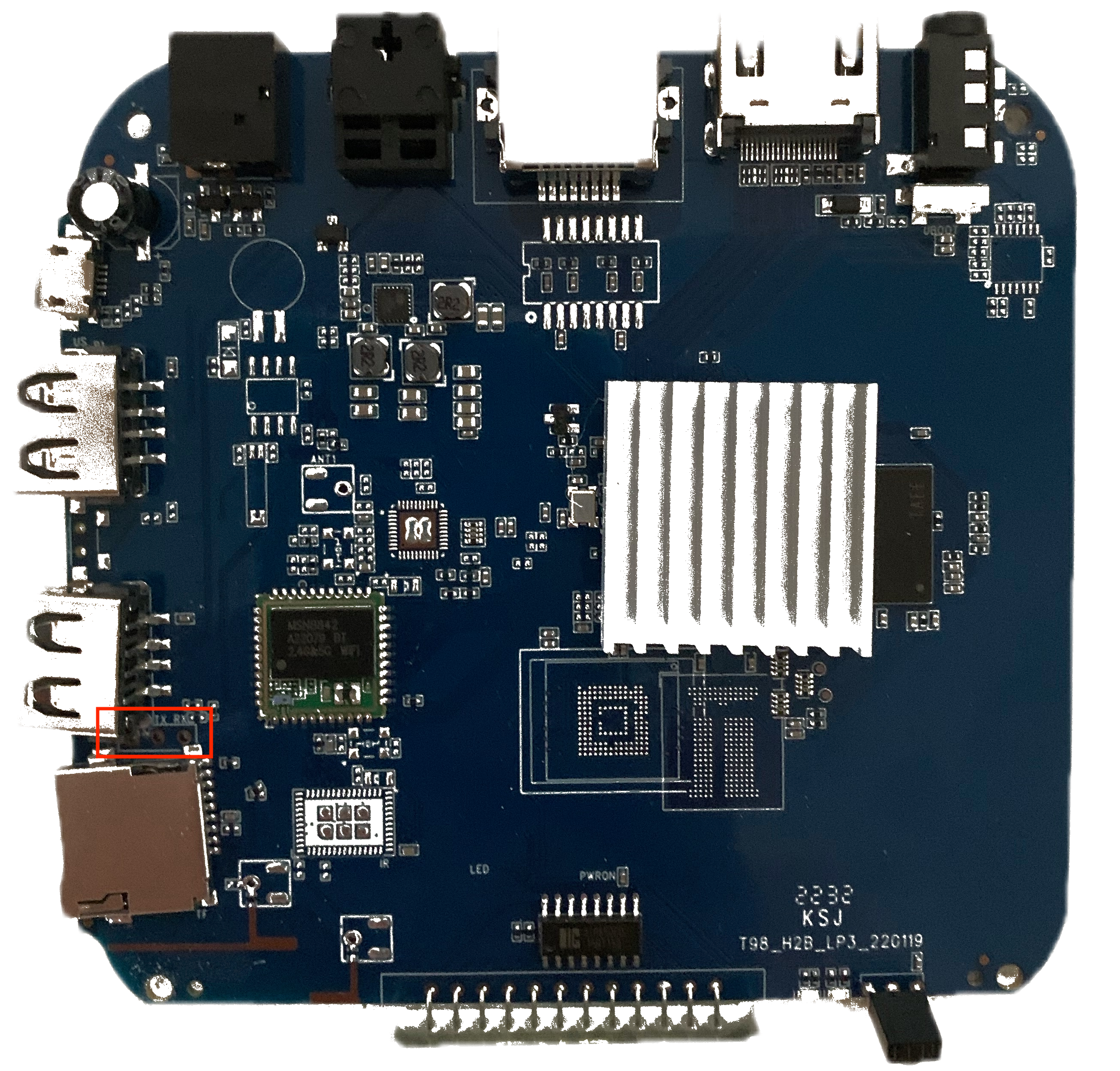
After removing the feet, opening the enclosure and taking out the PCB, the UART interface was easy to spot. RX and TX were actually marked on the board, so no detective work was needed this time.
Wiring it up with a Flipper Zero
I used a Flipper Zero as the USB-UART bridge between the TV box and my MacBook.
The wiring is simple:
TARGET TX  ─────────>  FLIPPER RX
TARGET RX  <─────────  FLIPPER TX
TARGET GND ──────────  FLIPPER GND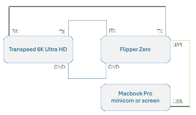
On the Flipper I selected GPIO → USB-UART Bridge and used:
115200 baud
8 data bits
no parity
1 stop bit
no flow control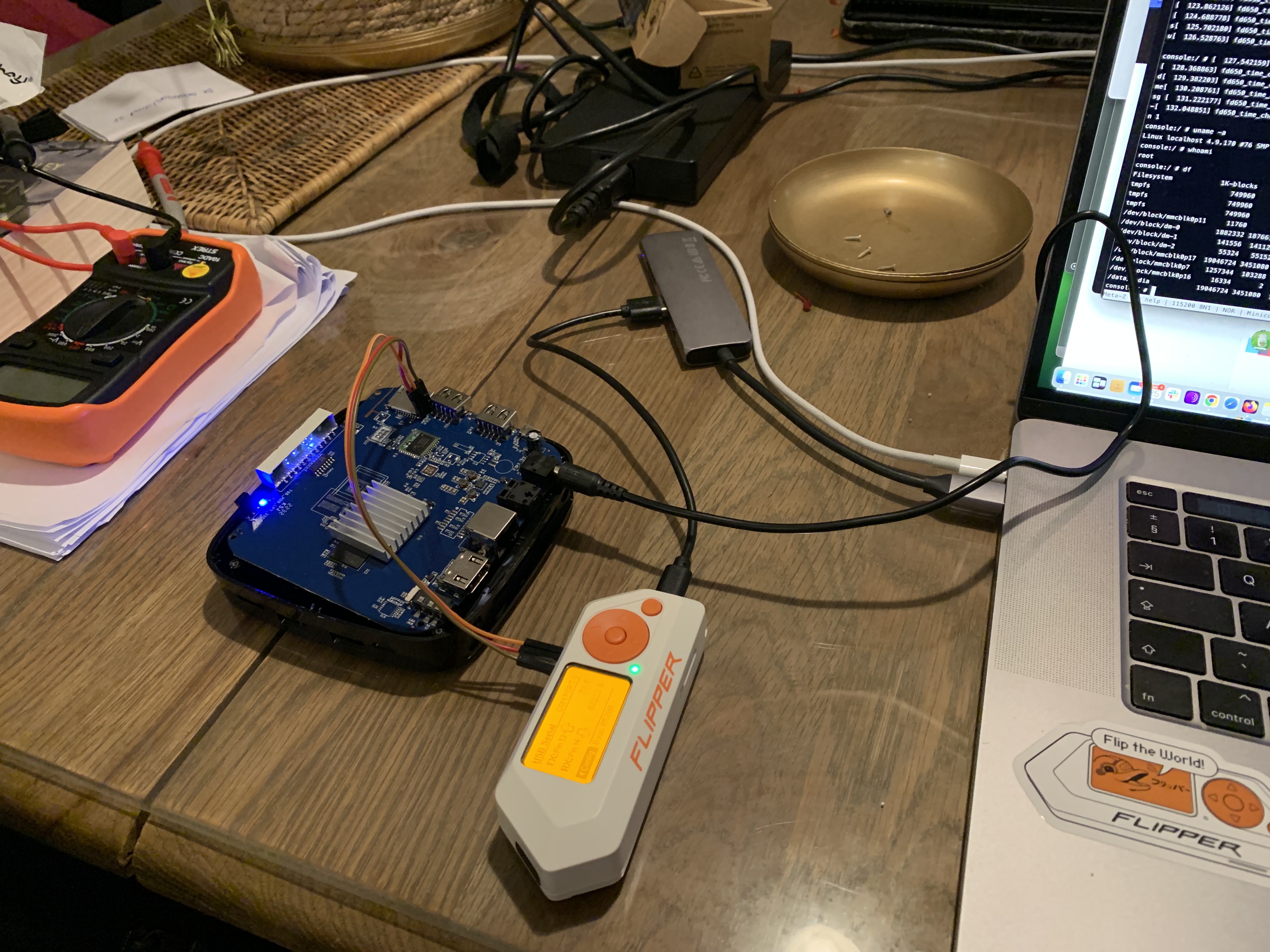
Configure minicom
On my Mac the Flipper serial device showed up as:
/dev/tty.usbmodemflip_On71nere1I started with:
minicom -sand configured:
+-----------------------------------------------------------------------+
| A -    Serial Device      : /dev/tty.usbmodemflip_On71nere1           |
| E -    Bps/Par/Bits       : 115200 8N1                                |
| F - Hardware Flow Control : No                                        |
| G - Software Flow Control : No                                        |
+-----------------------------------------------------------------------+
Save the configuration, start minicom, and power-cycle the TV box.
minicomIf everything is wired correctly, you should immediately start seeing boot messages.
And there is the shell
The Transpeed was noisy. Lots of kernel and Android messages kept flying over the console, but eventually I got:
console:/ $From there:
console:/ $ whoami
shell

console:/ $ su

console:/ # uname -a
Linux localhost 4.9.170 #76 SMP PREEMPT Mon May 30 13:44:11 CST 2022 armv8l

console:/ # whoami
root
At this point we have physical access to a root shell over UART.
The console was still being flooded with kernel messages, so I lowered the console log level:
dmesg -n 1That makes interactive work a lot less annoying.
A quick filesystem check looked like:
console:/ # df
Filesystem            1K-blocks    Used Available Use% Mounted on
tmpfs                    749960     628    749332   1% /dev
/dev/block/dm-0         1882332 1876612      5720 100% /
/dev/block/dm-1          141556  141120       436 100% /vendor
/dev/block/dm-2           55324   55152       172 100% /product
/dev/block/mmcblk0p17  19046724 3451080  15595644  19% /data
At this point I can inspect startup scripts, configuration, partitions, binaries and anything else that helps with the firmware research.
If the output is garbage
The first things I check are:
- baud rate;
- 8N1 settings;
- shared ground;
- whether TX and RX are crossed correctly.
Garbled output is very often just the wrong baud rate.
If I can read but not type
A debug header may expose target TX while the RX path is disconnected or disabled.
Double-check:
bridge TX → target RX
bridge RX ← target TX
ground ↔ ground
If the wiring is correct, inspect the PCB traces. Some vendors leave a readable console but deliberately break the input path.
If there is no UART at all
Not every production board gives you a usable serial console.
The UART function may be disabled in software, the header may be unpopulated, or the vendor may have cut/disconnected traces on the PCB.
That is when I move on to firmware extraction, flash access, JTAG or another route instead of spending another hour fighting minicom.
UART and firmware analysis work nicely together
I use both directions:
UART
  → watch boot
  → identify partitions
  → inspect services
  → pull configuration or firmware
  → validate runtime behavior

Firmware analysis
  → find startup scripts
  → find debug services
  → identify credentials / paths
  → know what to look for over UART
See Router Firmware Analysis Workflow for the software side.